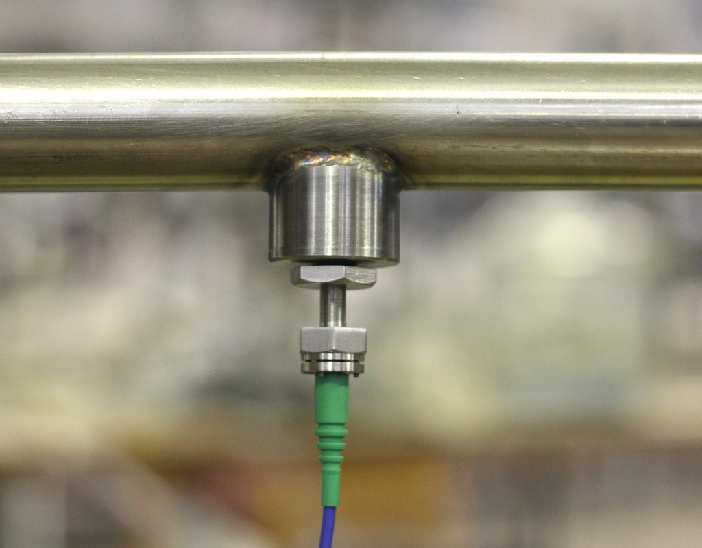
Wall shear stress measurements of oil flowing in a straight pipe were conducted at the Institute of Corrosion and Multiphase Technology at Ohio University. The test section of the flow loop in these experiments was a 1” inner-diameter pipe approximately 1 m long. The sensor (Model F-8K with +/-8kPa range) was installed flush with the wall at the middle of the test section on the bottom of the pipe. Britol 50T oil was used. Its viscosity (185 mPa-s at room temperature) was measured after completion of the tests using a falling ball viscometer. Wall shear stress values measured are presented as a function of the volumetric flow rate. All measurements were performed at a sample rate of 10 Sa/s. Estimated values were computed with the following formula, assuming fully developed laminar flow:
τ = \frac {4Uμ} {R}
where τ is the shear stress, μ is the viscosity, U is the average fluid velocity, and R is the pipe radius.
Multiphase Pipe Flow
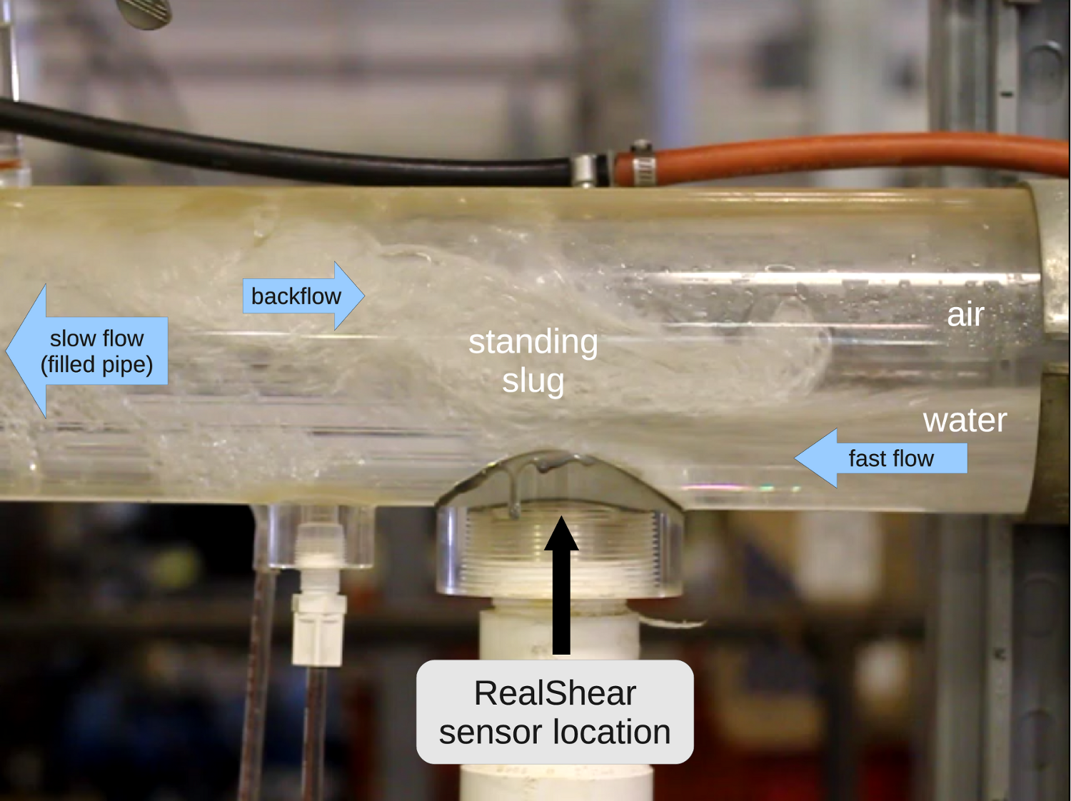
A RealShear™ sensor was used to measure the evolution of wall shear stress (WSS) in a “standing slug” experiment at the ICMT which consists of a slightly inclined pipe in which water and gas is introduced to form a stationary hydraulic lift. The position of the standing slug can be changed by careful adjustment of the gas flow rate. The wall shear stress was measured at the bottom of the Plexiglas 4” pipe, flush with the wall at a measurement rate of 1 kSa/s. Initially the slug was located downstream from the sensor (during the time interval between 0 and 5 seconds), then slowly passed over the sensor (5 to 9.5 seconds), becoming completely clear of the sensor after 9.5 seconds. A total of six independent measurements were taken, all providing similar results. There is a clear indication of the slug influence on the WSS. Instantaneous values of WSS (turbulences) in the slug are several times higher than those observed in the regular turbulent flow (when the slug is downstream of the sensor).
Flow in Thin Channels
Turbulent Water Flow
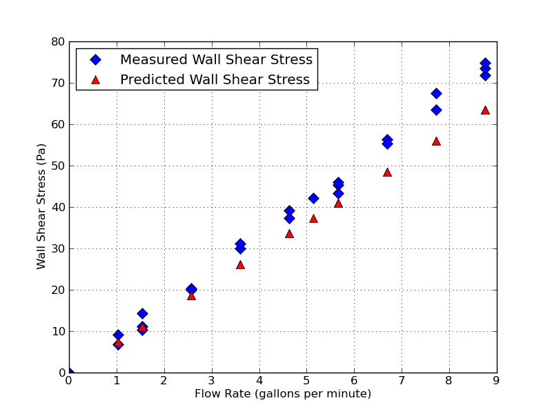
Wall shear stress measurements were made of water flowing in a rectangular cross section Thin Channel Flow Cell (TCFC) at the Institute of Corrosion and Multiphase Technology at Ohio University. An F-8K sensor was installed flush with the bottom surface of the channel. Tests with room temperature water were carried out using the following procedure. First, desired flow conditions were set up according to differential pressure gage measurements. The pressure difference was measured between two points before and after the flow cell. Then, flow was diverted to a bypass loop and a zero level for the sensor was recorded. The valves for the flow cell were then opened and bypass valves closed to divert flow back through the cell, flow in the cell was maintained for approximately 10 seconds to provide a measurement, after that the flow was redirected back through the bypass loop. Measured wall shear stress (WSS) values are plotted below as a function of the volumetric flow rate of the water. Expected values of wall shear stress are also shown calculated, assuming turbulent flow, from the following formula:
τ = f \frac {ρU^2} {8}
where τ is the shear stress, ρ is the fluid density, U is the average fluid velocity, and f is a friction factor related to the surface roughness of the inner walls of the rectangular channel. Wall shear stress predicted values are shown for surface roughness levels of 0.1 and 0.015 mm, which is the range in which the actual roughness of the polished stainless steel surface is expected to fall.
Additional details on experiments conducted at the Institute for Corrosion and Multiphase Technology at Ohio University are available per request.
Laminar Oil Flow
Tests of the RealShear™ sensor were carried out in another thin channel test station at the High-Shear Mixing Research Program (HSMRP) facilities at the University of Maryland. Laminar flow of an oil (Crystal Plus Oil 500 FG) was realized in a 2 mm high, 50 mm wide channel. Pressure drop was measured between two points 38 mm upstream and downstream of the sensor location as a cross-check. Flow rates between 0.5 and 7.5 L/min were realized during tests. Under the assumption of laminar flow, the wall shear stress can be calculated as:
τ = f \frac {6μU} {h}
where τ is the shear stress, μ is the viscosity, U is the average flow velocity, and h is the height of the channel.where τ is the shear stress, μ is the viscosity, U is the average flow velocity, and h is the height of the channel.
Measured and predicted shear stress as a function of flow rate for laminar oil flow in the thin channel experiment at the University of Maryland.