
RealShearTM Sensor: Measuring Wall Friction and Viscosity
November 9, 2021 2021-12-05 9:54RealShearTM Sensor: Measuring Wall Friction and Viscosity
RealShearTM Sensor: Measuring Wall Friction and Viscosity
Measuring Viscosity
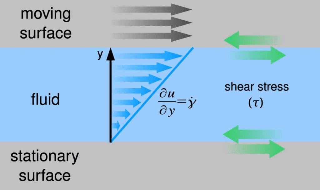
Wall shear stress (WSS) and viscosity are interrelated through the shear rate (velocity gradient) of a fluid:
τ = μ\frac {du} {dy}=μγ
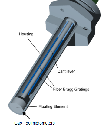
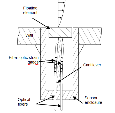
Here τ is the shear stress, γ is the shear rate, μ is the dynamic viscosity, u is the velocity component of the fluid tangential to the wall, and y is the distance from the wall. Lenterra’s RealShear™ sensor directly measures shear stress at a wall . To determine viscosity the value of the shear rate at the wall must be independently known. The viscosity is then given by:
μ = \frac {du} {dy}=\frac {τ} {γ}
If the shear rate is known or can be modeled, a RealShear™ sensor can be used as a real-time, in-line viscometer. Measuring viscosity in this way uses the same principle as “cup-and-bob” viscometers in which a cylinder is rotated inside a cup, submerged in the fluid under test. This powerful capability of RealShear™ sensor removes the need for further costly instrumentation when viscosity needs to be monitored in-line.
Example 1: Viscosity Measurement in High-Shear Mixers
High-shear mixers are used across numerous industries, including for the production of pharmaceuticals, food, and cosmetics. They can provide significantly shorter mixing cycles to radically improve throughput compared with conventional mixers. HSMs are often of the rotor-stator type, in which one element (the rotor) rotates in close proximity (as small as 0.2 mm) to a stationary element (the stator). Mix components that pass between them experience high shear stress.
For high-shear mixers, the known rotor geometry and rate of rotation can be used to calculate the velocity gradient. The velocity gradient profile is linear due to very small gaps between the rotor and stator. Under this assumption, the shear rate at the stator is simply the tangential velocity of the rotor (the “tip speed”) divided by the gap distance between rotor and stator:
γ = \frac {rotor velocity} {gap}
The rotor velocity can be calculated from its diameter, d, and the rate of rotation (RPM):
rotor velocity= π\frac {RPM} {60}d
Using wall shear stress measurement from RealShear™ sensor, τ, the viscosity can be calculated as:
μ= \frac {60} {π}\frac{gap}{RPM}τw
Example 2: Viscosity Measurement in Pipes and Channels
Measurement of the wall shear stress can also be used to determine the viscosity of fluids flowing through pipes or other channels. Just as in the case of high-shear mixers, in order to calculate the viscosity from the measured wall shear stress, the wall shear rate must be known. Formulas exist that implicitly incorporate the wall shear rate for various channel geometries and can be used to calculate the viscosity based on the measured wall shear stress.
The flow is fully developed (the velocity gradient no longer changes as the flow continues). This condition can be assumed to occur at a distance into a pipe equal to several pipe diameters, or a distance into a thin channel equal to several channel heights. When the flow is fully developed, viscosity can be calculated using simple formulas given below for circular and rectangular channels.
Circular Cross-Section Pipes
Viscosity can be calculated from the wall shear stress measured on the wall of a pipe with a circular cross-section with the following formula:
μ = \frac {τr} {4U}
Here U is the average flow velocity in the pipe, and r is the inner radius of the pipe. To calculate the average flow velocity from the flow rate, one can simply divide the volumetric flow rate (Q) by the cross sectional area of the pipe (A): U=Q/A

Thin Rectangular Cross-Section Channels
In thin channels (in which the height of the channel is much less than its width such as those found at the exit zone of extruders), viscosity is calculated as
μ = \frac {τh} {6U}
Where h is the height of the channel, and U is the average fluid velocity that can be found after measuring the flow rate.
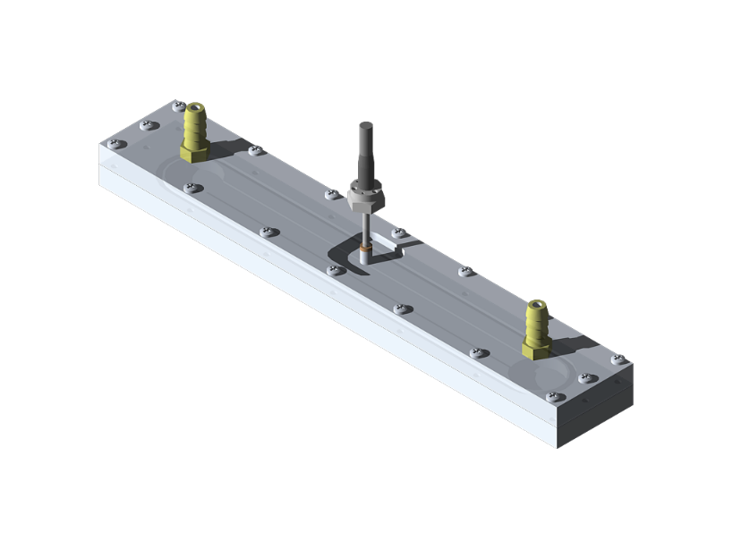
Wall shear stress in a standard flow cell
Wall shear stress is well modeled for a fully developed flows. Such a flow can be realized in a standard rectangular profile flow cell with a RealShearTM sensor installed on a particular distance from the input port wher the fully developed flow conditions are realized. Wall shear stress in this arrangement is directly measured and viscosity of the fluid is reliably calculated.
Temperature Measurement
For both Newtonian and non-Newtonian fluids, viscosity is dependent on temperature. For some fluids, even small changes of temperature can result in significant variation in viscosity. As a consequence, accurate interpretation of viscosity measurements should be accompanied by temperature measurements. Lenterra’s sensors are unique in their ability to simultaneously measuring force/shear stress and temperature.
Other approaches are available to calculate the viscosity using RealShearTM sensor for different flow geometers and when the flow is turbulent. Please contact us for details.